![]()
Published February 1, 2015 by Scott Allen Burns

3D Movie Audience (Cropped photo by woody1969 CC BY-NC-ND 2.0)
3D movies have been around for decades. Some of the earliest ones required the audience to wear red/blue or red/green glasses to filter the appropriate parallax-shifted image to each eye. More modern movies use polarizing filters, which allow the movie to be in color.
The 3D Shadowlamp illuminates objects with red and green light, casting shadows that appear 3D when viewed through colored glasses. (Click to enlarge.)
This project concerns a simple device that projects live 3D images onto a wall, ceiling, or projection screen. It does this by casting multiple shadows using two colored light sources that are offset from one another. The two light sources are high-power LEDs, which provide a small enough light source to cast a relatively sharp shadow.
One LED is red, producing shadows surrounded by red light. The other LED is green, producing shadows with a green surround. The two shadows are offset by an amount that depends on how close the object casting the shadow is to the LEDs. The colored glasses permit only one of the two colors to enter each eye, giving rise to the sensation of depth.
I unexpectedly ran across this idea when researching color theory on the web. Wendy Carlos called the image a 3D Shadowgraph, but that name has already been taken, so I decided to call the device a “3D Shadowlamp.”
I introduced this device to my extended family at a recent Burns family reunion, and gave out a couple dozen of them:
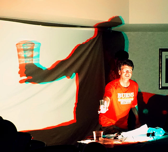
The shadow is 3D when viewed through red/cyan glasses.
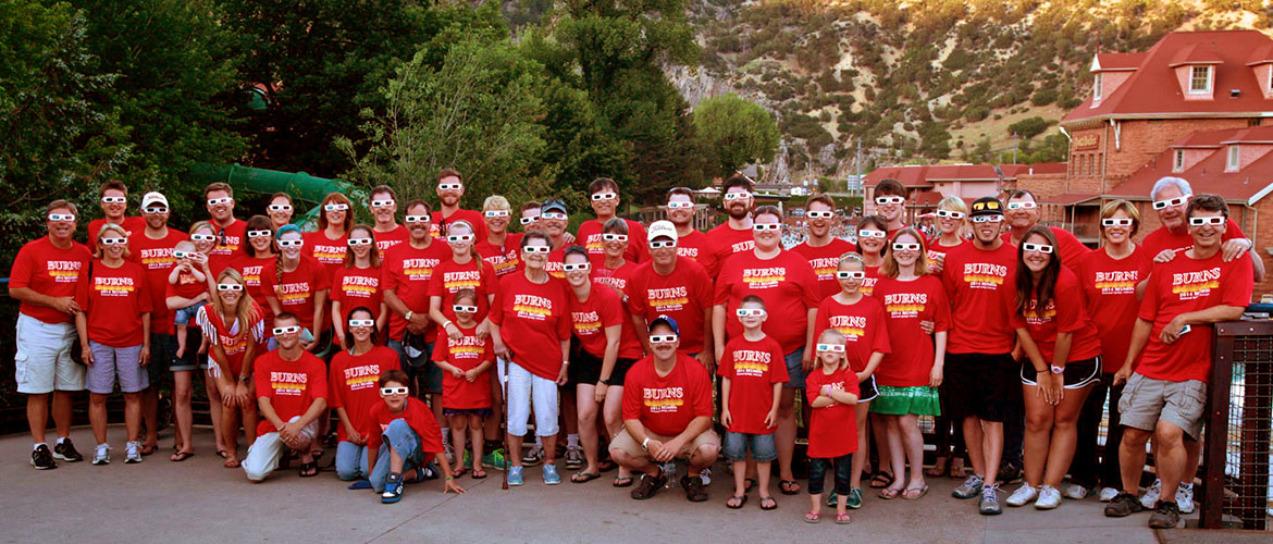
2014 Burns Family Reunion (Photo credit: Dawson Swan)
Construction
It’s a relatively inexpensive and simple project to build. The parts needed are:
- a red 700mA LED, such as this one
- a green 700mA LED, similar to the red one above
- two heat sinks to dissipate the LED heat (sorry no source for these, you’ll have to improvise!)
- heat sink compound or thermally conductive tape, such as these
- three 4.7 ohm, 2 watt resistors, such as these
- 22 gauge stranded wire to solder to the LEDs, such as this
- 14 gauge solid wire for the support structure, such as this
- three small gray wire nuts to connect the circuit, and one large red one to secure the support structure, such as these
- a small cable tie or twist tie to hold all the wires together
- a 5v power supply capable of providing at least 1.2A, such as this one
- red/cyan glasses, such as these
Tools needed are:
- wire cutters
- soldering iron to attach wires to the LEDs
Here is the circuit. It’s not very energy efficient, but it certainly is simple and inexpensive:
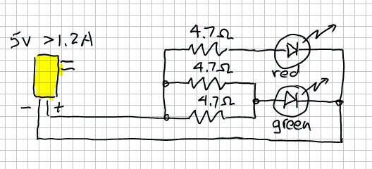
3D Shadowlamp Circuit.
Notice that I’ve used three identical resistors, where I could have used two different ones instead. I did this because it is more economical to buy multiple resistors of one type than small quantities of different resistors (unless they come in some sort of assortment kit). This circuit will pass approximately 600 mA through each LED, assuming the LEDs are on the low end of their voltage drop range. If they have higher voltage drop, there will be somewhat less current flowing.

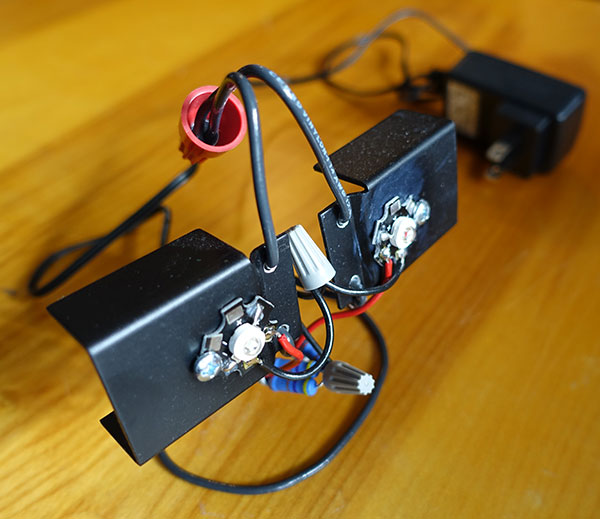
The current limiting resistors are tucked underneath the device (click to enlarge).
The resistors will get pretty hot, which is why I specify the 2W variety. Higher wattage resistors will be fine, of course. I connected the resistors using the small gray wire nuts, and tucked them under the device to lessen the chance of touching them when hot. The resistor connected to the red LED will get the hottest, as it is dissipating up to 1.7 watts of power.
The thicker 14 gauge wire is used to form the base and to support the two heat sinks, to which the LEDs are attached with either heat sink compound or adhesive thermally conductive tape. The large red wire nut ties the ends of the heavy wire together and also forms a handle.
In this photograph, the red LED is on the right and the green one is on the left. The red/cyan glasses should be worn with the red lens over the left eye and the cyan lens over the right eye. This will make the shadow of objects closer to the Shadowlamp appear closer to the viewer.
Another alternative is to illuminate a screen from behind (e.g., a bedsheet) and cast shadows on the back. Viewers on the other side will see only the shadows in 3D, and not the objects casting the shadows. Either the glasses will have to be worn backwards, or the Shadowlamp will have to be turned upside-down for the correct depth effect to happen. Otherwise, objects closer to the Shadowlamp will cast larger shadows but the parallax will be telling the brain they are farther away, leading to contradicting stimuli.
If you make one of these and have images of how you used it, please post links to the photos in the comments. Enjoy!
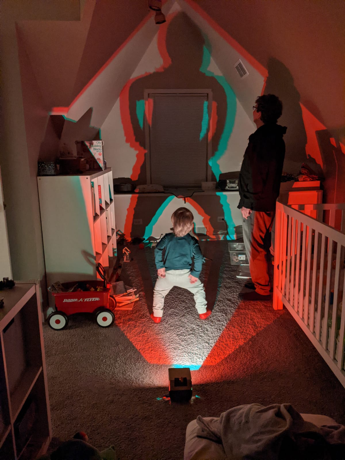
Playing with the shadowlamp with my grandson!
________________________________________

3D Shadowlamp by Scott Allen Burns is licensed under a Creative Commons Attribution-ShareAlike 4.0 International License.
This is great. Thank you for sharing this information.
Now let me ask, how about just getting two bright LED flashlights (one red and one green or blue) and mounting them together? Can that work?
If not, do you think you could post a video on a site like YouTube showing how to put this together?
Thank you.
I guess it would be worth a try! Your best bet is to remove the flashlight’s reflector behind the LED so that it doesn’t emit a narrow beam of light, and so that it acts more like a point light source. Let me know if it works!