Published January 16, 2015 by Scott Allen Burns; last updated August 15, 2015
Theo Jansen is known for his “Strandbeest” walking mechanisms made of plastic tubes that are powered by the wind and roam the shores of The Netherlands. Many people have created variations on his design using the eight-bar mechanism that forms each leg. Usually, there are a large number of parallel legs needed to keep the walking device stable.
I have developed a version that only needs four legs. I used a mathematical optimization technique to design the legs to make this possible. Here is the device in action:
Design
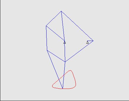
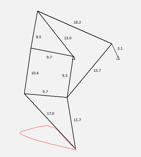
Here is the starting design. It was a trial and error process to find a mechanism that behaved roughly as a walking mechanism.
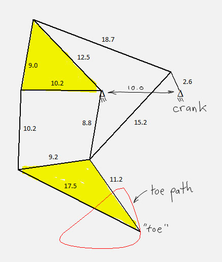
This mechanism is uniquely defined by the 11 line segment lengths and the distance between the two supports:
This mechanism belongs to the “8-bar mechanism” category because it contains 8 rigid bodies (5 line elements, two triangles, and the ground element). One of the links is designated the “crank” and its motion is controlled by a motor. A “toe” point is defined on one of the elements and it traces out a “toe path” as the crank makes a full revolution.
My goal was to adjust the lengths of the 11 line segments so that the toe path had a desired shape, specifically, a flat portion on the bottom that accounted for at least one half of the crank rotation, and the remaining portion sweeping above the flat portion. This type of toe path will produce a good walking gait.
To achieve the desired toe path, I employed mathematical optimization, sometimes called nonlinear programming. The optimization statement comprises an objective function and a set of constraints. Both the objective and the constraints are functions of the design variables, which are the 11 line segment lengths in this case. The distance between the two support pivots is held fixed at 10 units.
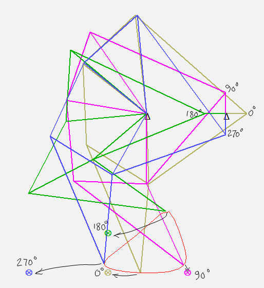
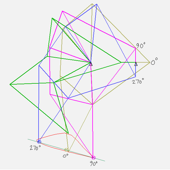
To formulate the objective function, I defined four “precision points,” depicted by the ⊗ symbol in the following figure:
This figure shows the mechanism in four different positions, corresponding to four crank angles. I wanted to adjust the 11 line segment lengths so that the toe point was as close as possible to the precision point for each of the four crank angles. The arrows I’ve drawn on the figure indicate where I want the toe point to be for each crank angle. Thus, the objective function is simply the sum of the distances between the actual toe point and the precision point. This is the quantity I want to minimize. In an optimal solution, that sum would be zero, meaning that the toe point passes exactly through each precision point.
The constraints I defined for this optimization ensure that the area of each triangular region will not collapse to zero. In other words, wherever there are three line segments that form a triangle, the sum of the lengths of any two segments must be greater than the length of the third segment. This helps the optimizer from wandering into regions of the design space that contain defective mechanisms.
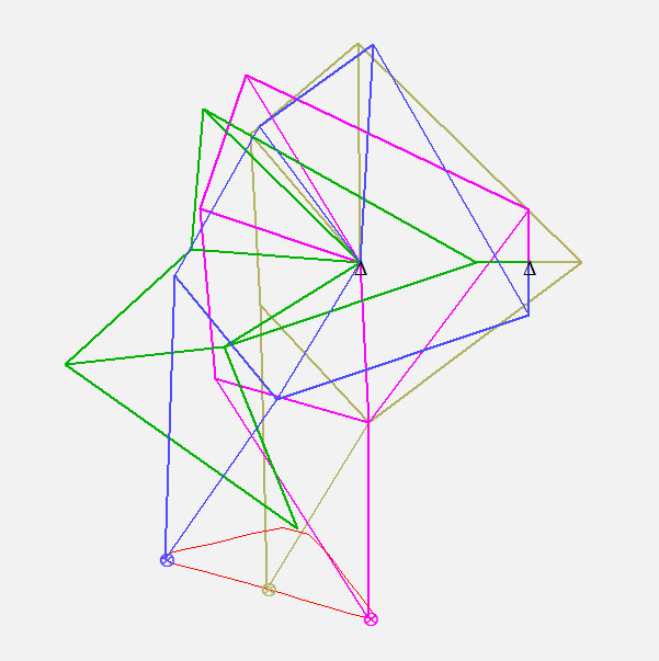
Numerical optimization is more of an art than a science, in my opinion. Usually, the process requires some intervention to prevent the process from exploiting mathematically valid, but physically meaningless excursions into the design space. I prefer to monitor the optimization process and cherry-pick fortuitous events, while rejecting obviously bad moves. In this case, the first iteration of the optimization process gave rise to a nice-looking toe path. Further iterations led to less desirable shapes. Here is the result of the first optimization iteration:
Although the toe path is not very close to the desired precision points, it has nice characteristics when viewing the mechanism in a rotated configuration. I wanted to flatten out the lower portion of the toe path, so I defined some new precision points:
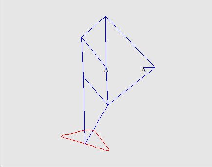
These new precision points formed a straight line with equal spacing over 90 degree crank rotation. After a few more optimization iterations, I arrived at this design:
The lower portion of the toe path is now delightfully flat and encompasses a full half-turn of the input crank. Plus, the toe raises a good distance above the flat portion during the other half-turn of the crank, which will help the device step over obstacles. Here is this final design animated:
Stability
As mentioned earlier, most re-designs of Theo Jansen’s walker require many parallel leg mechanisms because the “flat” portion of the toe path is actually somewhat curved. Overall stability of walking is achieved by having each leg in contact with the ground over a relatively small interval of the crank rotation. My design allows stable balance when only two legs are in contact with the ground, assuming the legs are wide enough to satisfy a static equilibrium condition. But I’m getting ahead of myself. First, let’s talk about how to arrange the four legs.
Here are the line segment lengths for the optimal design:
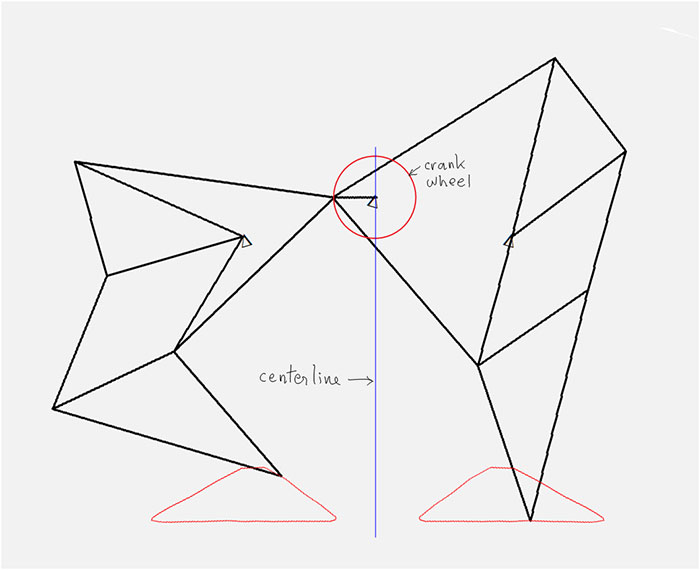
Theo Jansen’s designs show how two legs can be placed side-by-side on the same crank, mirror images of one another, to produce a cooperative walking gait:
This eliminates one degree of walking instability by having one toe on the ground at all times.
BTW, the mechanism was rotated 16.1 degrees in order to make the flat part of the toe path horizontal. Before rotation, recall that the two support pivots were 10 units apart horizontally. After rotation, the horizontal distance between the central leg pivot and the vertical centerline becomes 10*cos(16.1 deg)=9.61 and the vertical distance between the two pivots becomes 10*sin(16.1 deg)=2.77. This is important information when it comes time to build one of these.
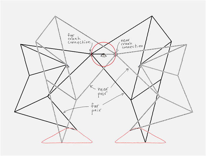
Another degree of instability is eliminated by having two pairs of legs working together, 180 degrees out of phase:
At any instant, there are two toe points in contact with the ground. By making the toe link sufficiently wide, the parallelogram formed by the two lines of toe contact always contains the center of gravity of the walker, thus ensuring static stability:
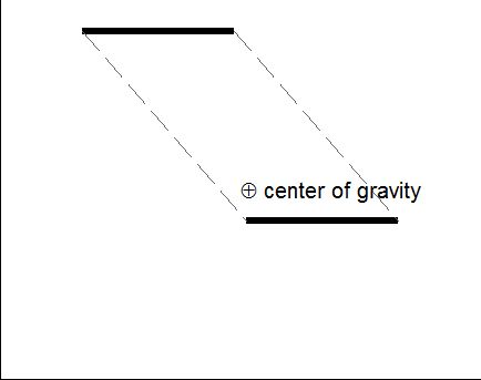
Top view of lines of toe contact, enclosing the center of gravity at all instants. (Roll mouse over to animate.)
Construction
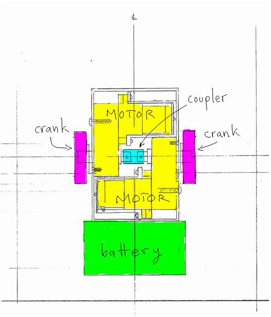
Two gear motors drive the two crank wheels. The motors have drive shafts that protrude from both sides, so they can be coordinated to move together by using a shaft coupler:
The motors are oppositely wired so that they turn the two crank wheels in the same direction. A battery pack (4 AA) is suspended from below the body.
The leg mechanisms are cut by hand from sheets of 1/8″ Sintra (expanded PCV) board. The hinges are formed from gaffer tape and the shafts (1/16″ brass rod) pass through teflon tubing hot glued to the Sintra. The four links that connect to the crank wheels are 1/16″ brass rods with an eyelet bent by hand on each end.
In a subsequent project, I was also able to create this walking device using a 3D printer instead of building it from hand cut pieces.
If you have any questions about this project, please feel free to comment below.
________________________________________

Four-Legged Theo Jansen “Strandbeest” Walking Mechanism by Scott Allen Burns is licensed under a Creative Commons Attribution-ShareAlike 4.0 International License.


Hello,
First of all, i’d like to tell you that I find your walker very great, so great that i tried to construct one from the views on the utube video. Today, i discovered this site and understood that i was far from the truth, cause i used Theo Jansen measurements to build my prototype.
I’d like to try a second one, but analyzing your drawings, it appears to me it misses two measurements to complete the data: the number of units between the pivot of a leg and the centerline, and the number of units from the pivot of the crank and the horizontal line that join the pivots of front and rear legs. You would be very kind to give me a hint with this issue.
Thanks,
Philippe
Hi Philippe,
Yes, you are correct that I forgot to present an important piece of information: the leg is rotated 16.1 degrees to make the flat portion of the toe path horizontal. I’ve updated the presentation to include that data. That means the 10 unit distance between supports, which was originally horizontal, is now rotated 16.1 degrees as well. Thus the horizontal distance between the pivot point on one leg and the vertical center line becomes 10*cos(16.1 deg)=9.61 and the vertical component of the distance between the two supports is 10*sin(16.1 deg)=2.77. Thanks for your feedback! If you eventually build one, I’d be delighted to see photos or videos of it.
Scott
Scott,
Can you show some formulas to determine the minimum width of the foot link to ensure the center of gravity stays within the parallelogram formed by the diagonally opposed legs? Would the formula change any for a two-legged walker being pulled like a cart?
PT
I don’t know of any formulas for that. What I did was simply construct a polygon connecting the edge points of each foot in contact with the ground. (More formally, it would be the convex hull of the two lines of contact of the two legs contacting the ground.) If that polygon contains the center of gravity, then it should be statically stable. This design would not be suitable for a two-legged cart because when one leg tries to lift off the ground, the device would pivot about the hitch point and tilt over, always keeping both legs in contact with the ground.
Sir can i able take turn or i can able to steer the mechanism theo jansen
I wish I could steer it, but alas, it only walks in a straight line.
I would assume that it could turn if you reversed the direction of one of the motors – or would this cause balance issues?
Yes, you’re right, balance issues would ensue. That’s why the two motors are firmly coupled to each other: to keep the center of gravity within the parallelogram that their contact points form.
As per my thinking we can only able to ta take turn but not at any angle but at axis on which it is moving and another axis perpendicular to it by using two ….
I can better tell u this by using images i have made give me ur email id i will email u it
Mail me your thoughts
Mail:- pulipakavijay@gmail.com
Excellent engineering. I’m reinventing the same wheel at present for fun!
I’d be delighted to see what you come up with!
Can anyone think of a way to make this turn? Having one set of legs go faster than another would not work because they would get out phase. Perhaps having the front two legs on one motor and the back to legs on the other, and then rotating the front legs? Or maybe having one side go forwards and the other backwards?
Its a great idea but im confused, you printed it?
No, I cut this one by hand from sheets of Sintra. But then later, I 3D printed one, but didn’t show it here.
what material did you use for the links of the mechanism? something light, cheap and easy to find, please suggest
I used 1/8″ expanded PVC sheets (known as Sintra) for the links. I cut them by hand with a utility knife, using multiple light to moderate pressure strokes. For the edge joints, I used gaffer tape. For the revolute joints, I hot-glued teflon tubing (small segments) to the plastic Sintra sheets, and then ran 1/16″ brass rod through the tubing. It gave a pretty effective low-friction connection.
Hi,
Nice job with your design and optimization for 4 legged motion. Do you have the digital files for your 3D print? Also, if I were to scale up a similar design to, let’s say about 3 feet tall, do you think I could achieve a similar result to what you did? (I was planning to use a combination of corrugated cardboard and chipboard since they are quite cheap and sturdy) Do you think the overall weight might be too much for the mechanism to hold up and move?
– Isaac
No, sorry, I don’t have any 3D files available. I would imagine you could scale it up to 3′ tall. You’d need larger motors and batteries, of course. You’d probably want to use bearings and a heavier set of shafts, and perhaps actual hinges for the edge joints, instead of just cloth tape.
Thanks for the tips!
i am a final year mechanical engineering student. we have been assigned the similar project from our university. but we are confused how to proceed. what about turning. it will be great if you can provide help. we have to make a walking bicycle. how to make joints of legs?
This device isn’t designed to turn, and I’m not sure how you’d go about doing it. See the article and descriptions in the comments for more info on how the joints are made.
do you have the kinematic analyses ?
I am doing this project and I need some help. Contac me.
how can a wiper motor be used to rotate the crank in this project? can you please help me out with the gear ratios? will gear motors be available in a scrap yard? if yes then which?
I’ve not tried wiper motors before, but I imagine they have enough torque to run a small version of this walker. As far as gear ratios, you just have to decide if the speed of the gear motor output is what you want. I suppose you could add additional gears to change the speed, but that would greatly increase the complexity of the build.
hey I have used 1 inch by 1 inch GI tubes to make the links and used M8 nuts and bolts to join them by drilling holes into the links but the project doesn’t seem to stand up, it continuously falls back down as the links don’t remain how they are supposed to, is it that the freedom given by the bolts to the links is too much? o is it just that the weight of the links is too much? please help me and suggest what can be done to hold it up, also suggest if I should replace the nuts and bolts and what I should fit in to hold it tights as well as give necessary movement
*1 inch by 1 inch square tubes
Hi, I am currently trying to build a strandbeest myself by I didn’t really understand how you got your numbers for the length of the segments. Did you use any form of formula? If yes could you show me?
I understand your approach using the points for the 90, 180, 270, 360 angles to let the foot pass through, but I do not comprehend how you put these into relations with the lengths of the segments.
Thanks!
KG
I’m afraid it’s not as simple as using a formula. It takes advantage of a field of math/engineering called optimization. It requires that we formulate an “objective function” and a set of “constraints,” which are all functions of the design variables (the lengths of the eleven line segments). To solve the formulation, we use one of the many optimization algorithms that have been developed over the years (for example, the Solver Add-In in Excel uses one called the “GRG” method). This article would have to be about ten times as long to thoroughly cover all the details of the design formulation and solution process. I used to present this example in detail in the senior-level engineering course I taught (Engineering Design Optimization) before I retired. I consider this article to be an overview of what is possible once optimization tools are understood. A good place to get started is any textbook on engineering design optimization. Here’s one that is available online: http://www.apmonitor.com/me575/index.php/Main/BookChapters
Thank you very much! I’m currently doing this as a project in highschool and was overwhelmed by the maths. I don’t think I can comprehend this method in such a short period and I will probably use computer simulations to optimize the lengths manually instead. But nevertheless thank you for your reply!
Takes me back to an optimization class I attended in circa 1977 at WPI. A facinating subject. Thanks.
Hi! This is a very nice strandbeest! I have to make one for a school project, do you mind if I use yours to help me? Really nice work you’ve got here!
Thanks! If you do end up making one, post pictures please!
Hello sir,
I make this project almost complete but i am stuck at battery stage that how can i calculate power and how to set battery.
I hope that you will help me..thank you.
I don’t calculate power. I simply use four AA batteries in a rectangular holder like this one: https://smile.amazon.com/Tactic-Cell-Battery-Holder-Connector/dp/B002I9V60E/ref=sr_1_19?ie=UTF8&qid=1519734294&sr=8-19&keywords=4AA+battery+holder
Which motors did you used , can I use toy motor and the dimensions in which image shown above is perfect of mechanism please reply as soon as possible. Thank you.
I bought them from Solarbotics.com. I’m not sure if it was https://solarbotics.com/product/gm2/ or https://solarbotics.com/product/gm8/. Probably the first one for the higher torque, if I recall correctly.
Hello Scott,
Whenever I came across a video of Jansen’s Strandbeests, I’ve been wondering if anybody explored the toe path space. Thank you very much for sharing a step in this direction. I wanted to ask if you are aware of other references analyzing this space (I’d naively guess that there are different regions, maybe with boundaries defined by non-smooth toe path etc.). Also the momentum (normalized by the crank) of the toe would be interesting (e.g. to maximize for a fun-looking paddle boat propulsion).
Thanks,
Steffen
Hi Steffen,
It is indeed a fascinating subject of study. My explorations in the design space have been pretty limited. No, I’m not aware of studies of that nature. I like your idea of trying to identify bounded regions of feasible toe paths and mechanically efficient designs. If you make advances in these areas, please send links to your work!
Scott
Hello, what kind of wires did you use?
Thx
and crank? We are trying to create a strandbeest out of popsicle sticks and we are stuck on how to use a motor and connect it to the legs to make it work.
By “wires” I assume you mean the rods used as link members and axles. They are both 1/16″ dia brass rods, and can be purchased from most any hobby store. (e.g., https://www.hobbylobby.com/Crafts-Hobbies/Hobbies-Collecting/Tools-Blades/Brass-Rods—1-16/p/24134)
The crank is made from a wheel that is made specially for the motor.
motor: https://solarbotics.com/product/gm2/
wheel: https://solarbotics.com/product/gmw/
i am working on a prototype of rough terrain bot and would like to implement this, can this mechanism be modelled to climb on inclined surface and small obstacles. Any help would be appreciated,thanks
This design is best suited to horizontal flat surfaces, mostly because it relies on downward acting gravity to maintain stability. It will step over small obstacles, though.
are these dimensions in mm?
The dimensions given are in arbitrary units. I set the distance between the two supports to be 10 units, and all the other dimensions are relative to that. To work in a preferred system of units, like mm, just multiply all the dimensions by the same factor until you have a desired scale. If you apply a scale factor of 4 to all dimensions, then that will be pretty close to the size of the example in the video, in mm.
Hi Scot,
Wow! Your use of the optimization process to predict a flat toe path was truly a mathematical tour de force!
This year, I am planning to make a stradebeest with my introduction to robotics students. In the past, we have used
24VDC power wheelchair bases and their motors to make many different moderately sized, powered parade floats, about 60 cm wide, 120 cm long and up to 3 m tall. Here is a question for you, What if we used two gear motors that were not coupled together and varied the speed between them with a motor driver and an RC radio? This is how we control our parade floats.
Would changing the speed of the motor controlling the legs on one side relative the the other enable the beest to turn?
Please advise and thanks.
Sten
The only problem with decoupling the two motors is the stability issue. By coupling them, I can guarantee that the center of gravity remains within the parallelogram defined by the two lines of contact with the ground. I don’t think that would be the case it the two sides moved independently. If the CG falls outside that parallelogram, it will fall over.
What are the factors to be considered while designing Theo Janson mechanism.There should be some factors.
I discuss what I consider to be the main factors in the article above. Or do you mean something else when you say “factors”?
Equally important to flatness of the motion of the foot when in contact with the ground is whether it moves at a constant rate. From looking at the animation, at seems that the rate is a little slower at the ends of this contact interval compared to the middle. If there are other legs driving the device at the same time, this would result in some sliding of the feet while it walks.
I don’t observe any sliding in the video, though. If it’s there, it’s very slight.
Good observation! Yes, I agree, it’s not perfectly uniform, but doesn’t seem too bad. (I consider this design to be more of a “proof of concept.”) I suppose additional optimization constraints could be implemented to try to even out the motion…
How to calculate force required to move the Theo Jansen mechanism with certain weight and torque of a motor to actuate the mechanism
Calculations of this type are beyond the simple kinematic analysis I performed. It would depend on many factors, such as the friction in all joints and type/quality of construction. I don’t have an easy answer for you.