![]()
Published January 12, 2015 by Scott Allen Burns
The goal of this project was to build a Segway-style balancing machine (sometimes called an inverted pendulum) using simple off-the-shelf parts. Normally a balancer requires sophisticated circuitry and sensors, like microprocessors and accelerometers. This one uses only:
- a radio-control (RC) transmitter and receiver kit (like those used for RC cars and planes)
- a servo motor (link)
- an infrared range detector (Sharp model GP2Y0A02YK0F link)
- one 2.2k ohm resistor
Here is a video of the device in action:
How it Works
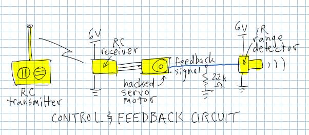
The RC transmitter and receiver supply a fixed PWM signal to the servo motor.
Normally, a servo motor would use this PWM signal to position the output shaft, using an internal potentiometer to sense the position. Here is what is inside a generic servo motor:

The servo motor is modified by removing the mechanical stop on the output shaft (so it can rotate continuously), and the potentiometer is also removed. A feedback signal wire is connected to the place where the potentiometer’s wiper used to connect:

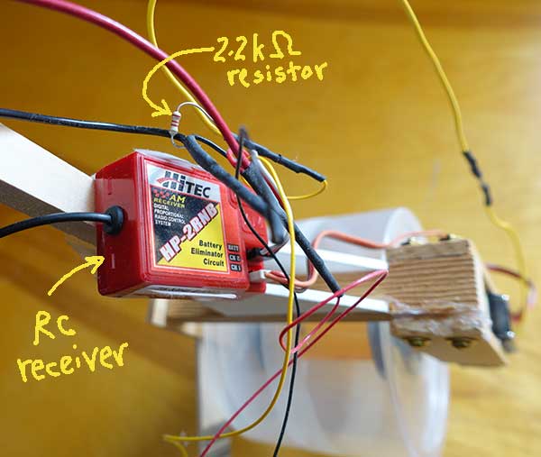
This new connection is routed out of the servo motor and is connected to the signal line of the IR range detector, using a pull-down 2.2k ohm resistor to match signals. Now, instead of sensing the position of the output shaft, the servo motor senses the distance from the IR range detector to the ground.
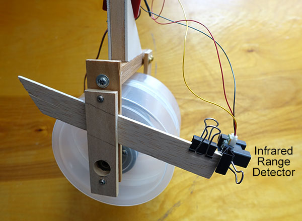
Side view of wheel and adjustable IR detector.
The range detector is mounted so that its distance/angle with the ground can be adjusted. This serves two purposes. The first is to adjust the distance to the ground so that the wheel doesn’t rotate when the device is upright and in static equilibrium.
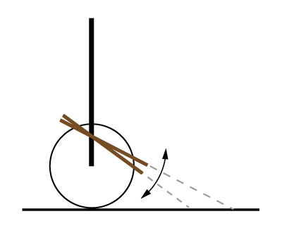
Rotate the IR detector so wheel stops when device is upright.
The second purpose is to mechanically adjust the “gain” on the feedback signal, or how fast it changes with changes in the orientation of the device. Too shallow of an angle, and the control system over-reacts and gets unstable and shaky. To large of an angle, and the control system can’t react fast enough to changes in position and loses balance.
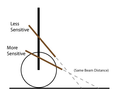
Adjust sensitivity by changing angle beam makes with ground when balanced.
It takes some trial and error to get the right angle.
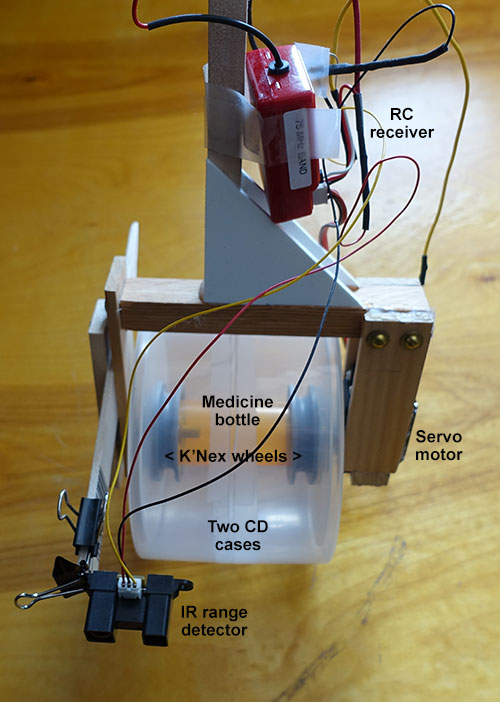
The main wheel is made from two CD cases taped together. To ensure that the servo motor torque is transmitted solidly to the wheel, two K’Nex wheels are glued to a medicine bottle. The servo motor output shaft is screwed through the CD case and into one K’Nex wheel. The other K’Nex wheel is attached to a hollow brass tube that protrudes out of the CD cases and into a ball bearing support embedded in the wooden frame:
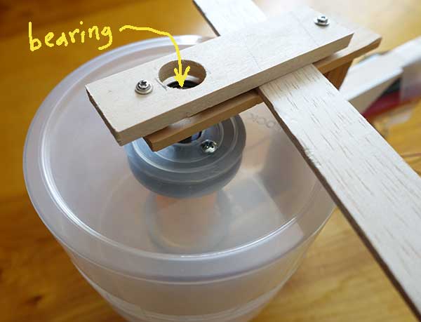
The hollow tube allows a long screwdriver to pass all the way through the large wheel assembly to tighten or loosen the screw connecting the servo motor to the wheel.
The RC receiver is mounted on the vertical stem:
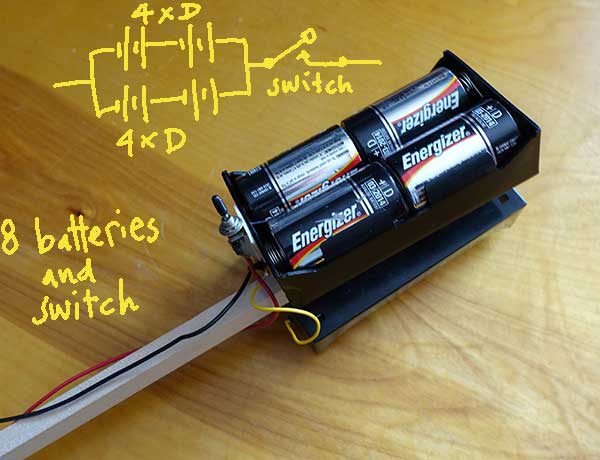
Eight D batteries are used to make sure enough current is available for the servo motor when it needs to provide lots of torque. Two groups of four batteries in series are wired in parallel, providing 6 volts to the receiver, servo motor, and range detector. The batteries are placed at the very top of a long vertical post to make balancing easier.
The RC transmitter has a trim adjust lever:

This is useful to fine tune the PWM signal so the balancer stands upright and doesn’t roll. By moving the trim lever, the balancer can be made to start rolling in one direction or the other. This is the main reason why the RC set is used instead of a simple PWM generating circuit on the balancer, which would be much less expensive, but would require frequent adjustment and would have no ability to externally control rolling movement.
________________________________________

Segway-Style Balancer by Scott Allen Burns is licensed under a Creative Commons Attribution-ShareAlike 4.0 International License.