Published January 27, 2015 by Scott Allen Burns (last updated May 27, 2023).
BLIFNAR stands for “blinky lights for no apparent reason.” I’ve had one in my window for a couple decades, greeting me every time I happen to walk by it at night. During the day, it charges up by solar power; at night, it blinks–a nice soothing type of blink that bursts to life and then slowly decays. It it could make a sound, it would probably be something like “PUMMmmmm. That’s why the BEAM Robotics community calls a device like this one a “pummer.”
Here it is in action:
Back in the ’90s I taught a class called “Creative Mechatronics” that introduced students to the joys of the “maker” movement. This was one of the projects we built.
I’m going to first give instructions on how to build one, and then discuss how it works for those who are interested.
Construction
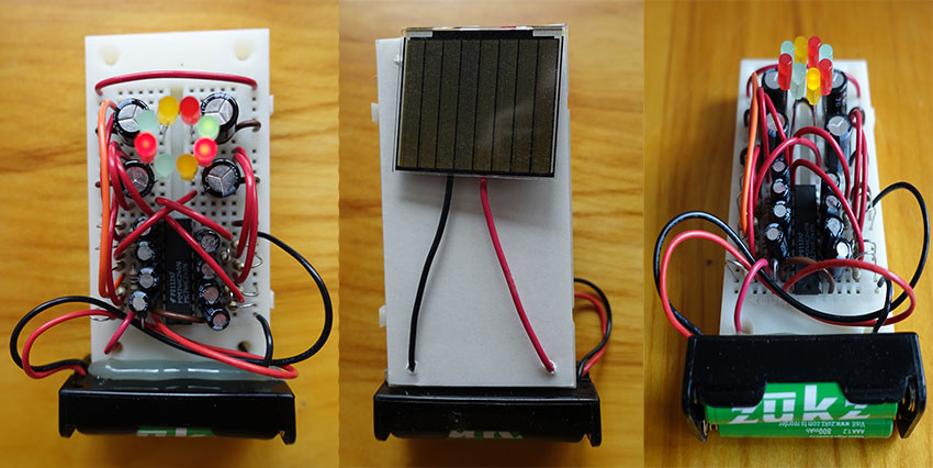
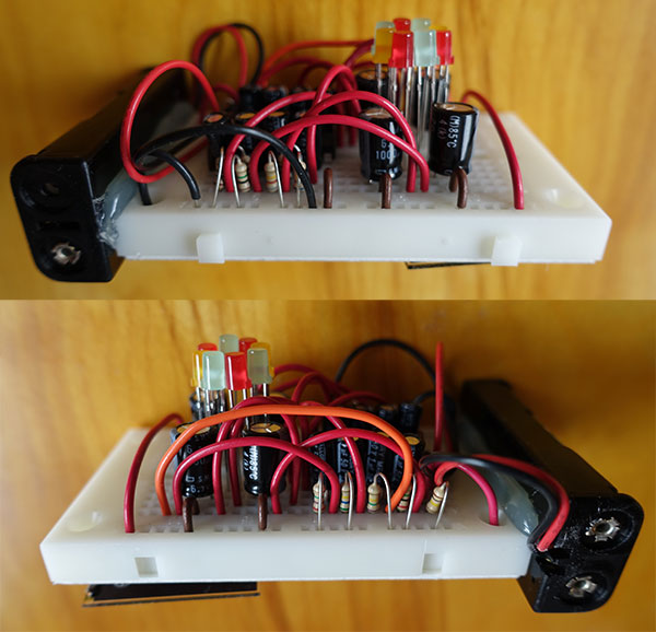
Here are the parts needed:
- a 3.4v solar cell, such as this one
- a 270 point solderless prototyping board, such as this one
- a 74HC240 integrated circuit, such as this one
- a two-cell AAA battery holder, such as this one
- two AAA Ni-MH rechargeable batteries
- four 1000 uF electrolytic capacitors, such as this one
- eight 1 uF electrolytic capacitors, such as this one
- eight red/yellow/green LEDs, such as this one
- a 1N34A germanium diode, or a diode with a small forward voltage drop
- a 100k ohm resistor
- four 1M ohm resistors
- eight resistors of assorted resistance, in the range 500k ohm to 7M ohm
- a bunch of jumper wires
These tools will be needed:
- wire cutter or scissors to trim the leads of the resistors and capacitors
- hot glue gun or other type of glue to connect the battery pack to the prototyping board
- if the solar cell does not come with wires attached, then a soldering iron is needed to attach them
This PDF file lists the construction steps. The “location” listed is the pair of hole locations identified on the prototyping board. The placement of the 74HC240 isn’t listed on the PDF, but it should be placed on the proto board with pin 1 in hole F1, spanning the E and F rows.
Be sure to use red, yellow, or green LEDs. The blue and white ones have forward voltages that are too high for this circuit. A forward voltage of 2.2 to 2.3 volts seems to work well.
The eight assorted resistors will control how fast the LEDs will flash, and how “random” they will appear. Smaller resistances will give faster flashes. Try various combinations to find a pleasing flash pattern.
After supervising the construction of almost a hundred of these circuits by students, I’ve noticed that sometimes not all eight LEDs will flash when the circuit is very slowly activated at sunset, having instead only six, four, or two of them flashing. It appears that certain combinations of the eight resistors causes this. If you experience similar symptoms, try rearranging the eight assorted resistors or select a different mix of values. This has always solved the problem in my experience.
The BLIFNAR will work best if placed in a sunny window with the solar cell pointed outside. Enjoy!
Circuit
This circuit was inspired by designs posted to the BEAM Robotics community in the early 2000s. The circuit comprises two independent parts. Here is one half of the entire circuit:
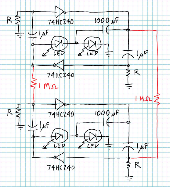
Portion of the circuit driving four of the eight LEDs. This subsection is repeated for the other four LEDs.
It contains two sub-subsections that each drive two LEDs. The two sub-subsections are loosely coupled through two 1M ohm resistors. The outer loop of each sub-subsection is a relaxation oscillator that flips the halves of the loop between high and low at a rate determined by the two resistors labeled “R.” Inside the loop are the two LEDs and a large capacitor responsible for lighting them up. Each time the outer loop switches states, a doubled voltage is presented to one of the LEDs, which exceeds its forward voltage and causes it to light up and then dim as the large capacitor charges or discharges. This circuit is repeated for the other four LEDs, using the remaining four gates of the ‘240 inverter IC.
In total, there are eight “timing” resistors, R, in the entire circuit. Different patterns of flashing are obtained by selecting different combinations of R resistors chosen from the range 500K to 7M ohms. The lower the resistance, the faster the flash.
Power to the oscillator is supplied by the gates, which get their power from the two batteries (via +V and ground):
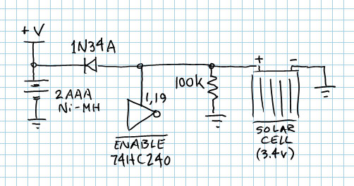
The circuit subsection responsible for powering the circuit and sensing when it is dark and time to flash.
The solar cell is attached to the two enable pins on the 74HC240 (pins 1 and 19, enabled when low). When it is dark, the solar cell is unable to provide enough voltage to overcome the 100k ohm pull-down resistor, and enables the IC. The 1N34A diode prevents the battery from killing the enable action, and also provides a pathway for the solar cell to charge the battery when it has light on it. A low voltage drop on the diode makes the charging more efficient. A Schottky diode could probably be used instead. A regular switching diode might even work, perhaps with a somewhat higher-voltage solar cell to compensate for the higher voltage drop.
Improvements
I feel there is much room for improvement with this circuit, for example:
- The 1 uF caps should probably be non-polarized, like a monolithic version.
- The specific solar cell I provide a link to is somewhat undersized for charging the AAA batteries. I find that every year or so I need to take the batteries out and recharge them externally. A larger solar cell would probably be better, but I’m concerned that if it has a substantially higher voltage, it might cause problems with operation.
- I need to investigate other options for the 1N34A germanium diode. It is somewhat difficult to find and there may be more modern options available. Also, I should investigate how important it is to have a low voltage drop on the diode–maybe a simple switching diode would be fine.
- I need to scope the circuit when it is acting up (not all LEDs are flashing) to better understand the cause. Perhaps I could arrive at rules of thumb for selecting the eight assorted resistors to avoid the problem.
I don’t know if I’ll manage to get to any of these “wish list” items. If you have experience with circuits and can provide insight, please comment below!
________________________________________

BLIFNAR by Scott Allen Burns is licensed under a Creative Commons Attribution-ShareAlike 4.0 International License.